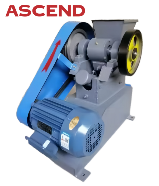
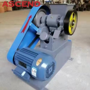
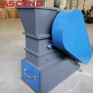
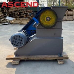
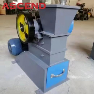
Ascend lab jaw crusher crusher limestone granite hard stones for testing
Products video
Spare part

Specification
|
Model |
Max feeding size(mm) |
Capacity (kg/h) |
Output Size (mm) |
Power (KW) |
Dimension (mm)(L*W*H) |
Weight (kg) |
|
PE100*60 |
≤50 |
230-400 |
6-10 |
1.5 |
950*400*550 |
85 |
|
PEF100*60 |
≤50 |
45-550 |
0.1-15.1 |
2.2 |
1050*410*765 |
260 |
|
PE100*100 |
≤80 |
200-1800 |
3-25 |
3 |
1050*410*860 |
320 |
|
PEF125*100 |
≤80 |
200-1800 |
5-25 |
3 |
1050*410*860 |
320 |
|
PE150*100 |
≤90 |
400-3000 |
6-38 |
3 |
1050*410*860 |
360 |
|
PEF150*125 |
≤100 |
400-3000 |
6-38 |
3 |
1050*410*860 |
360 |
Production advantages
(1)Unique crushing cavity to make the jaw plate material utilization rate is higher.
(2)Crushing cavity jaw plate tooth peak relative (movable jaw plate and fixed jaw plate), is more conducive to breaking the more hard materials.
(3) Transmission angle adjustable structure design, in the case of the same discharge port production is higher.
(4)The fixed jaw plate and the movable jaw plate are universal, which can effectively reduce the number of the user's spare parts,and make the installation more convenient.
(5) The movable jaw and the frame part can be split structure to facilitate the transportation.
Packing and Shipping


